Linear motors create straight-line motion directly, rather than converting a rotating shaft’s movement through gears or belts. That direct drive can make a machine simpler. It can also bring precise positioning, quick acceleration, and fewer mechanical parts that wear over time. Yet the label “linear motor” covers several designs, and their differences matter in real applications.
Some motors use an iron core to produce strong force in a compact space, while ironless designs reduce magnetic attraction and cogging. Flat and U-channel motors describe common track and coil arrangements; tubular motors package the magnetic components around a rod. These categories can overlap, so a product’s shape alone does not explain how it performs. Not always. Motor operation matters, too: synchronous designs can provide tightly controlled motion, while induction designs suit different requirements and control methods. The right choice depends on more than speed or force.
This guide compares the main types of linear motors, how they work, and where their strengths become useful. A factory gantry, for example, may need fast travel and repeatable stops, while a laboratory stage may prioritize smooth, low-vibration movement. Engineers should also consider payload, travel distance, heat, environmental conditions, drive compatibility, and maintenance access. A specification sheet can narrow the options, but it cannot replace testing under actual loads. That is worth remembering. No design is best in every setting; the practical choice balances performance, cost, and the compromises a project can accept.
Linear motors differ by how they create thrust. An induction linear motor uses a moving magnetic field to induce current in a conductive reaction plate, producing force without direct electrical contact. It suits conveyors and transport systems, but the air gap and plate heating can affect efficiency. A synchronous linear motor instead keeps the magnetic field of the mover aligned with the stator field. This gives precise position control and strong thrust at low speed, useful in machine tools and automated assembly. The design needs accurate control. Small alignment errors matter.
Other principles solve different problems. Voice-coil motors use current-carrying coils interacting with permanent magnets; they offer smooth, short-stroke motion in optical stages and test fixtures. Linear reluctance motors generate force by pulling iron toward a changing magnetic field, though control and vibration can be challenging. The categories can overlap in real machines, so labels alone may mislead. The International Energy Agency’s Energy Efficiency 2023 report estimates that motor-driven systems account for about 53% of global electricity use. That figure covers many motor applications, not linear motors alone, but it underlines why operating principle, duty cycle, and heat losses deserve careful comparison. I would still check performance at the actual stroke and speed, not just a catalogue rating.
Linear induction motors (LIMs) create motion without a rotating shaft. Their primary winding produces a traveling magnetic field, which induces current in a conductive reaction plate or rail. The resulting force pushes the moving part forward. No mechanical contact is needed between those components. That gap matters. It also makes air-gap size and alignment important: a rail that sits unevenly can reduce thrust and increase heating. At higher speeds, end effects can weaken the magnetic field, so LIM performance depends on the motor’s length and operating conditions.
LIMs suit applications where direct, contact-free movement is useful, such as conveyors, automated handling, and some transport systems. Their trade-offs deserve attention. The reaction rail adds weight, and induced currents can produce heat; efficiency varies with design, speed, and load. The U.S. Department of Energy’s 2014 Improving Motor and Drive System Performance sourcebook reports that motor-driven systems account for about 68% of electricity use in U.S. manufacturing. That figure covers motor systems broadly, not LIMs specifically, so it should not be treated as a LIM efficiency estimate. For a real installation, engineers should measure energy use, temperature, payload, and duty cycle under actual operating conditions. A paper calculation alone can miss the awkward details.
Linear synchronous motors (LSMs) create straight-line motion using a moving magnetic field. Coils in the stator are energized in sequence, pulling or pushing a mover along a track. The mover may carry permanent magnets or field windings. With suitable electronic control, it travels in step with the magnetic field rather than relying on rotary motion and a mechanical screw. Smooth movement is possible. Precise timing matters.
LSMs suit applications that need controlled travel, such as automated handling lines or positioning equipment. A mover can accelerate quickly and stop at a chosen point, but the system still needs careful design. Track alignment, heat, payload, and control settings all affect performance. One detail is easy to underestimate: a small alignment error can cause vibration or uneven force. And installation isn’t effortless. Engineers should check the full motion profile, not just the motor’s peak force. Actual results can differ from ideal calculations.
Tips: Match the motor and controller to the load, speed, and duty cycle. Keep the air gap consistent, and monitor temperature during testing. If motion feels rough, inspect alignment before increasing power. That simple check is often useful.
Linear stepper motors convert electrical pulses into small, discrete movements along a straight path. A controller sends pulses to the motor, and each pulse advances the carriage by a set distance. This makes them useful in compact stages, dosing equipment, and desktop machines where repeatable positioning matters more than high speed. No encoder is needed for basic open-loop operation, though a missed step can go unnoticed.
Their appeal is straightforward control. But performance depends on load, acceleration, friction, and step resolution; a carriage may vibrate or lose position if pushed too hard. Grand View Research’s 2024 Linear Motor Market report estimates the overall market at USD 1.67 billion in 2023, with projected growth of 7.4% annually through 2030. This covers multiple linear motor types, not stepper motors alone, so it signals broader demand rather than stepper-specific sales. That distinction is easy to miss.
Tips: Check thrust and travel speed under your actual load, not just the motor’s no-load rating. Keep the guide aligned, and test acceleration with the real payload. A little margin helps.
Thrust generally decreases as speed increases. This illustrative curve is not a specification; actual performance depends on the motor, driver, supply voltage, and load.
Common Linear Motor Designs and Configurations
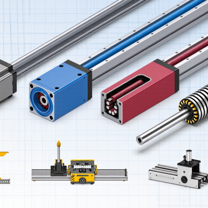
Linear motors create motion directly along a straight path, without converting rotation through a screw or belt. Their designs suit different loads, speeds, and working environments. Iron-core flat motors provide strong thrust and suit demanding stages, though magnetic attraction can increase bearing loads. Ironless designs avoid that attraction and reduce cogging, making them useful for smooth, precise scanning. They generally deliver less force for a given motor size. A trade-off.
Tubular motors place the coil and magnets along a cylindrical axis. Their compact form can fit pick-and-place equipment, but heat removal and mounting need careful attention. Flat motors may use a single-sided or double-sided magnetic track; the latter can balance magnetic forces. Some systems move the coil while others move the magnet assembly. That choice affects cable routing, moving mass, and maintenance access—not just motor performance.
The International Federation of Robotics reported 541,302 industrial robots installed worldwide in 2023 in World Robotics 2024. The figure describes robot installations, not linear-motor use, but it shows the scale of automated motion applications where linear axes may be selected. For a real machine, compare continuous and peak thrust, stroke length, acceleration, cooling, and encoder resolution. A catalog’s maximum speed is not the whole story. A long stroke with a heavy carriage may need a different configuration than a short, fast inspection axis. Teams sometimes overlook cable flex and alignment; both can undermine an otherwise precise setup.
| Motor Type or Configuration | How It Produces Linear Motion | Typical Motion Characteristics | Common Advantages | Considerations | Common Applications |
|---|---|---|---|---|---|
| Iron-Core Linear Synchronous Motor | A three-phase coil assembly interacts with a permanent-magnet array. The magnetic attraction between the magnets and iron core contributes to thrust. | Direct-drive, electronically commutated motion; available in short or long travel configurations. | High force density and strong thrust for a relatively compact motor assembly. | Magnetic attraction can create normal force on the guide system. Cogging and thermal management may also need consideration. | Machine tools, packaging equipment, automated production lines, and long-travel positioning systems. |
| Ironless Linear Synchronous Motor | A coil assembly without an iron core interacts with a permanent-magnet track to generate thrust. | Direct-drive motion with low cogging and smooth force over the working range. | Low detent force and no iron-core attraction between the motor coil and magnet track. | Typically provides less force per motor volume than an iron-core design; coil cooling and magnet-track cost may be important. | Optical inspection, semiconductor equipment, precision stages, and laboratory automation. |
| Tubular Linear Motor | Coils and permanent magnets are arranged concentrically around a cylindrical axis. Depending on the design, the coil mover travels along a magnet rod or the arrangement is reversed. | Axial, direct linear motion in a compact, enclosed form. | Compact geometry can simplify integration where motion must follow a straight rod-like axis. | Force, stroke, cooling, and guidance depend on the specific tubular design; the motor does not by itself replace a complete load-bearing guide. | Pick-and-place equipment, material handling, test systems, and compact automation mechanisms. |
| Linear Induction Motor | An energized primary winding creates a traveling magnetic field that induces current in a conductive secondary, producing thrust. | Asynchronous motion; the secondary typically travels at a speed below the traveling magnetic field’s synchronous speed. | Can propel a passive conductive reaction plate without permanent magnets on the secondary. | Induced-current losses produce heat, and an air gap and suitable reaction plate are needed. Efficiency depends on the design and operating point. | Conveyors, material transport, sliding doors, and some transportation systems. |
| Switched-Reluctance Linear Motor | Sequentially energized coils attract a toothed or salient translator toward positions of lower magnetic reluctance. | Electronically switched motion; force is produced by controlled attraction rather than permanent-magnet interaction. | Can operate without permanent magnets and can tolerate high temperatures in suitable designs. | Requires accurately timed switching. Force ripple, acoustic noise, and control complexity can be design challenges. | Special-purpose actuators, harsh-environment machinery, and applications where magnet-free construction is useful. |
| Voice-Coil Linear Actuator | A current-carrying coil moves in the magnetic field of a permanent-magnet assembly; reversing current reverses the force direction. | Direct, bidirectional force; commonly used for short-stroke movement and precise force control. | Fast response, smooth motion, and simple force control over a limited stroke. | Force is generally proportional to current within the operating range, so continuous force may require sustained current and heat management. It usually does not provide a long travel range on its own. | Camera focus and stabilization mechanisms, precision positioning, vibration control, and test equipment. |
Note: Linear motors may also be classified by topology, such as flat or tubular, and by operating principle, such as synchronous, induction, reluctance, or voice-coil. These categories can overlap; for example, a tubular motor may use a synchronous permanent-magnet design.