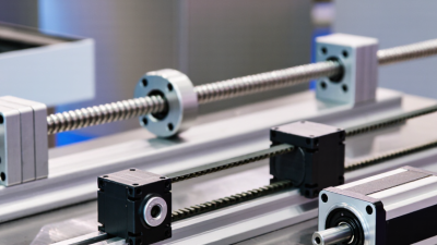
Choosing a linear motion system is rarely a simple catalog decision. The right solution must match the machine’s load, travel distance, speed, accuracy, and working environment. A compact rail may perform beautifully in a clean laboratory, yet struggle under dust, vibration, or repeated side loads.
Real engineering experience shows that small details often decide long-term performance. Check whether the carriage can handle the combined vertical and moment loads. Review acceleration, duty cycle, mounting flatness, and expected service life. A ball screw can provide excellent positioning accuracy, while a belt drive may offer greater travel speed and lower cost. Roller guides, profile rails, and polymer bushings also behave differently under contamination and maintenance limits.
Fit matters.
Reliable selection also requires evidence, not attractive specifications alone. Compare manufacturer load ratings, tolerance data, testing methods, and warranty terms. When possible, test the proposed linear motion system under realistic conditions, including the actual payload, cycle rate, temperature, and mounting structure. A design that looks efficient on paper may produce noise, heat, or premature wear in operation.
There is no universal best choice. Cost, precision, stiffness, maintenance, and installation time often compete with one another. Even experienced engineers can overlook cable routing or uneven assembly surfaces. That is why this guide examines each decision with practical criteria, measurable risks, and room for revision. The goal is not to select the most advanced system, but to choose one that remains dependable throughout its intended service life.
How to Choose a Linear Motion System?
Define the application before comparing rails, screws, belts, or motors. Record the required travel, payload, speed, acceleration, repeatability, and operating hours. A 600-millimeter stroke means little without the load profile. A carriage carrying 40 kilograms needs different guidance from one carrying 2 kilograms.
Start with the motion objective. Is the axis positioning a tool, transferring parts, or maintaining a steady process speed? Measure the real cycle, including pauses, reversals, and emergency stops. The International Federation of Robotics reported 541,302 industrial robots installed worldwide in 2023, showing how rapidly automated equipment is expanding. Linear axes must support this pace without sacrificing accuracy or service life.
Environmental details matter. Note dust, moisture, temperature, vibration, available space, and mounting orientation. Then calculate duty cycle and expected bearing or screw life using the supplier’s load equations and recognized engineering methods. ISO 9283 provides performance terminology for robot systems, but it does not replace application testing. Test the axis with the actual payload.
Do not over-specify blindly.
A faster axis may increase vibration, noise, and energy use. A tighter accuracy target may also raise cost without improving the finished product. In practice, engineers sometimes choose components before defining the process; that shortcut deserves review. A written motion profile makes weak assumptions visible and gives purchasing, design, and maintenance teams the same technical reference.
Choosing a linear motion system starts with comparing motion types, not catalog dimensions. Profiled-rail guides suit rigid, accurate travel under high loads. Round shafts tolerate contamination and simpler mounting, but usually sacrifice stiffness. V-wheel systems can reduce cost, although wheel wear may increase maintenance. In practical machine design, the environment often decides the winner. Dust, washdown, temperature, and misalignment matter as much as speed.
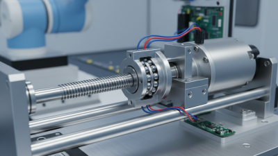
Drive mechanisms change the system’s behavior. Ball screws deliver strong thrust and repeatable positioning, especially for vertical axes. Their weakness is speed-related heat and limited travel length. Lead screws are quieter and cheaper, but they commonly move slower. Belt drives provide long travel and high acceleration. They may lose precision through belt stretch or tension changes. Rack-and-pinion drives support very long axes, though backlash requires careful adjustment. Linear motors offer exceptional acceleration and smoothness, but their installation and control demands are higher. Sometimes, the most advanced option is the wrong one.
Industry data supports a cautious approach. The International Federation of Robotics reported 541,302 industrial robots installed worldwide in 2023, showing continued automation demand. More automated axes also expose alignment and maintenance weaknesses. The U.S. Department of Energy identifies motor-driven equipment as a major industrial electricity user, so drive efficiency deserves attention.
A simple ranking can mislead. Compare total operating cost, not only purchase price. A spreadsheet may still miss vibration, lubricant contamination, or an operator’s daily adjustment time.
Sources: International Federation of Robotics, World Robotics 2024; U.S. Department of Energy, Motor Systems Market Assessment.
How to Choose a Linear Motion System?
Load capacity should be calculated, not guessed. Include the carriage, tooling, payload, acceleration, and external moments. According to the International Federation of Robotics’ World Robotics 2024 report, 541,302 industrial robots were installed globally in 2023. More automated equipment means more demanding motion cycles. A system that handles static weight may still fail under rapid acceleration. Check deflection, bearing life, and mounting stiffness. Small oversights become expensive.
Accuracy requires clear definitions. Positioning accuracy, repeatability, and straightness are different measurements. ISO 230-2 provides methods for testing positioning accuracy and repeatability in machine tools. Measure the real process target, not only the catalog value. Thermal expansion, vibration, and cable drag can shift results. In field commissioning, a clean laboratory specification often becomes less convincing. That is worth admitting.
Speed must match the duty cycle. A high peak speed may reduce life when acceleration is aggressive. Calculate travel time, pause time, and cycle frequency across the full stroke. The required stroke should include working distance, approach space, and safe overtravel. The 2024 robotics report also recorded more than 4.28 million industrial robots operating worldwide, showing how reliability now affects entire production networks. If application data remain incomplete, choose conservatively and validate with a prototype test. Perfect selection is rare. Measurement is better.
Evaluate load capacity, positioning accuracy, speed, and stroke before selecting a motion technology.
The chart compares representative performance levels for common linear motion technologies. Values are normalized against practical reference targets of 2,000 N load, 10 μm positioning accuracy, 1,000 mm/s speed, and 2,000 mm stroke. Higher scores indicate greater capability; accuracy is inverted so that a higher score represents better precision.
A linear motion system should be chosen for the environment it will occupy, not only its load rating. Measure dust, humidity, temperature, vibration, and cleaning methods before selecting rails or actuators. Coolant mist can enter seals. Fine powder can settle inside bearing paths. Frequent washdown may also demand suitable ingress protection under IEC 60529.
Integration deserves equal attention. Check mounting tolerances, cable bend radius, controller protocols, and available installation space. A system that fits mechanically may still create electrical or software problems. Leave room for inspection tools and manual access. Small details matter.
Maintenance needs should be visible during the design stage. The U.S. Department of Energy’s Operations & Maintenance Best Practices Guide reports that predictive maintenance may reduce costs by 8–12% compared with preventive maintenance, and 30–40% compared with reactive maintenance. These figures are useful, but they are not guarantees. Actual results depend on duty cycle, training, and data quality.
Specify grease intervals, seal replacement procedures, and accessible wear components. Add vibration or temperature monitoring when downtime is expensive. Record baseline noise after installation, then compare readings during each service visit. I have seen accurate systems underperform because technicians could not reach one lubrication point. That was a design failure, not a maintenance failure. Review the plan again after the first operating month. Real conditions often expose assumptions.
Selecting a linear motion system starts with real movement, not a catalog page. Define travel distance, payload, speed, acceleration, duty cycle, and mounting orientation. Record temperature, dust, washdown exposure, and installation space. A small gap matters. I have seen oversized systems waste energy, while undersized guides developed play within weeks.
Validation should combine calculations with physical testing. Estimate load life, deflection, friction, and motor torque under peak conditions. Check the complete axis, including couplings, supports, cables, and control settings. Then run a prototype through repeated cycles at the highest expected speed. Measure noise, heat, positioning error, and settling time. A spreadsheet may look convincing. Reality can disagree.
Optimization comes after stable validation. Reduce unsupported length, improve alignment, and select suitable bearings or drive components. Tune acceleration gradually instead of chasing maximum speed. Protect exposed surfaces with practical sealing and planned maintenance. Keep inspection points accessible. One overlooked cable bend can undermine an excellent mechanism. Document measured results, assumptions, and failure limits for independent review. Recheck the design when payloads or cycle rates change. The best system is conditional, not permanent.