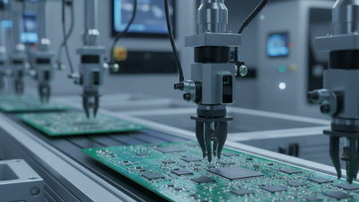
Motor control is the practical discipline of directing a motor’s speed, torque, position, and movement. It connects electrical power with mechanical work, from a quiet conveyor belt to a robotic arm stopping within millimeters. A suitable control method can reduce energy waste, limit overheating, and protect connected equipment. The choice matters.
Several types are available, including direct-on-line starters, variable frequency drives, servo drives, and stepper motor controllers. Direct-on-line starting is simple and economical, but it can create a strong current surge. Variable frequency drives adjust motor speed smoothly, making them useful for pumps, fans, and industrial conveyors. Servo systems provide precise feedback through encoders, while stepper systems offer controlled positioning without always requiring closed-loop feedback. Each option involves trade-offs in cost, accuracy, response time, maintenance, and installation complexity.
Reliable selection requires more than comparing product labels. Engineers examine the load profile, starting torque, duty cycle, voltage, environment, and required safety functions. A dusty workshop may demand a different enclosure than a clean laboratory. A high-inertia machine may also need braking control that a basic starter cannot provide. No single solution fits every motor. That is easy to overlook. This guide explains how motor control works, how major control types differ, and where each approach performs best. It also acknowledges an important limitation: real installations may behave differently from simplified diagrams, so manufacturer documentation, qualified testing, and measured operating data remain essential.
What Is Motor Control and What Types Are Available?
Motor control regulates speed, torque, direction, and position. These functions shape how a motor starts, moves, and responds under load. A direct-on-line starter offers simple switching and full starting torque. A soft starter reduces electrical and mechanical shock during acceleration. It does not provide continuous speed control.
Variable frequency drives adjust motor speed by changing frequency and voltage. They suit pumps, fans, conveyors, and many industrial machines. Servo systems add feedback from encoders, allowing accurate position and torque control. This matters when a mechanism must stop within millimeters, not merely reach a general location. The International Energy Agency estimates that motor-driven systems consume about 53% of global electricity. The U.S. Department of Energy also reports that motors may use more than 70% of industrial electricity. Efficiency decisions are therefore operational decisions, not only electrical ones.
Tips: Match the controller to the load profile. Check starting torque, braking needs, feedback accuracy, and heat dissipation. A large drive is not automatically safer. In practice, poor tuning can cause vibration, overshoot, or unstable speed. That lesson is easy to miss. A neat control diagram can still fail when cable shielding, grounding, or sensor placement is wrong. Review measured current, temperature, and response time during commissioning. Data should challenge assumptions, not decorate the report. Sources: International Energy Agency, Energy Efficiency 2023; U.S. Department of Energy, Improving Motor and Drive System Performance.
Motor control coordinates electrical power, feedback, and mechanical motion. A complete architecture connects sensors, controllers, drives, and motors. The sensor measures position, speed, current, temperature, or load. The controller compares these values with the required target. It then calculates a command for the drive. The drive regulates voltage and current before the motor produces torque. Every link matters. A weak sensor signal can affect the entire machine.
Open-loop control operates without continuous feedback. It suits simple movement, fixed-speed fans, and predictable loads. Closed-loop control uses feedback to correct errors during operation. It supports accurate positioning, speed regulation, and changing loads. Servo, stepper, and variable-speed systems can use different control methods. In practical commissioning, I have found that correct wiring alone is not enough. Sensor alignment, response settings, and mechanical stiffness also influence performance. No design is perfect. Noise, backlash, or an overloaded motor can still produce unstable motion. I sometimes focus too heavily on controller settings and overlook the coupling.
Tips: Place sensors close to the motion they measure. Keep feedback cables away from high-power wiring. Set current, speed, and travel limits before testing. Begin at low speed. Record stopping distance and temperature changes. Check the motor under a realistic load, not only during an empty test. A short test can hide a serious weakness. Recheck assumptions after installation.
Motor control determines how a motor starts, stops, protects itself, and responds to operating conditions. One widely used option is the across-the-line starter, also called a direct-on-line starter. It connects the motor directly to the supply voltage. The motor then receives full voltage immediately, producing strong starting torque.
That quick start has a cost. Starting current commonly reaches six to eight times the motor’s full-load current. For a 20-ampere motor, the initial demand may approach 160 amperes. This surge lasts briefly, but it can create noticeable voltage drop. Lights may flicker. Sensitive equipment may reset. Weak wiring can also cause excessive heating.
An across-the-line starter normally uses a contactor, overload relay, disconnecting means, and control circuit. The overload relay protects against sustained overcurrent, but it does not replace short-circuit protection. Correct adjustment matters. Set the overload protection from the motor nameplate data, not guesswork. During commissioning, measure current with a suitable clamp meter and observe the motor under its real mechanical load. A pump starting against pressure may behave differently from an unloaded fan.
This method is simple and reliable, yet it is not ideal for every installation. Frequent starts can stress couplings, shafts, and driven equipment. I have seen installations focus on motor size while overlooking voltage drop and restart frequency. That approach is easy to regret. When starting impact is unacceptable, reduced-voltage starting or electronic control may deserve closer review.
What Is Motor Control and What Types Are Available?
Motor control governs how a motor starts, stops, accelerates, and responds to changing loads. Two practical options are soft starters and variable frequency drives, or VFDs. A soft starter gradually increases voltage during startup. This reduces mechanical shock, belt strain, and current spikes. It does not provide continuous speed control. That distinction matters.
A VFD changes both motor frequency and voltage, allowing controlled speed throughout operation. In fans and centrifugal pumps, small speed reductions can create major savings because power follows the cube of speed. The U.S. Department of Energy reports that properly applied adjustable-speed drives can reduce energy use by approximately 20–50% in suitable systems. The result depends on load profile, piping resistance, control settings, and maintenance. The estimate is not universal.
The International Energy Agency’s 2011 report on electric motor-driven systems estimates that motor systems consume about 46% of global electricity. That figure explains why ramp control deserves serious attention. A soft starter may prevent damaging starts, while a VFD can reduce running energy during lower-demand periods. Field measurements remain essential. A poorly tuned VFD can waste energy through excessive pressure, harmonics, or bypass operation. The uncomfortable part is simple: expected savings may look impressive on paper, yet actual performance can disappoint. Engineers should record baseline power, operating hours, speed, and process output before judging the investment.
| Motor Control Type | Primary Function | Starting and Stopping Method | Speed Control During Operation | Typical Energy Impact | Common Applications | Important Considerations |
|---|---|---|---|---|---|---|
| Across-the-Line Starter | Connects the motor directly to the supply at full voltage. | Full-voltage, abrupt starting and stopping. | No variable-speed control; motor runs near its rated speed. | Normally no operational energy-saving function. | Small pumps, fans, compressors, conveyors, and machines with low starting impact. | High inrush current and mechanical stress may occur during starting. |
| Wye-Delta Starter | Reduces starting current by initially connecting motor windings in a wye configuration. | Stepped starting sequence followed by delta operation. | No continuous speed adjustment. | Usually little or no running-energy reduction. | Larger motors with suitable winding connections and relatively light starting loads. | Starting torque is also reduced; the motor and load must be compatible. |
| Soft Starter | Limits voltage applied to an AC motor during acceleration and deceleration. | Adjustable voltage ramp-up and ramp-down for smoother transitions. | Generally no continuous speed control after the motor reaches full speed. | Primarily reduces mechanical stress and peak starting current; it does not normally provide major running-energy savings. | Pumps, fans, conveyors, compressors, crushers, and machines needing smoother starts. | Bypass operation is often used after starting to reduce heat and semiconductor losses. |
| Variable Frequency Drive (VFD) | Controls motor speed and torque by varying output frequency and voltage. | Programmable acceleration and deceleration ramps with controlled current and torque. | Continuous speed control across an application-specific operating range. | On variable-torque loads, reducing speed can produce approximately 20–50% energy savings in suitable operating conditions; actual results vary. | Variable-flow pumps, fans, air handlers, conveyors, mixers, and compressors. | Requires correct motor, drive, wiring, cooling, harmonic, and electromagnetic-compatibility considerations. |
| Servo Drive | Provides closed-loop control of position, speed, and torque. | Highly controlled acceleration, deceleration, and motion profiles. | Precise variable-speed and positioning control using feedback. | Energy savings are application-dependent; its main benefit is motion accuracy and dynamic response. | Robotics, packaging, machine tools, indexing systems, and high-speed automation. | Higher system complexity and cost than basic motor starters or open-loop drives. |
| Direct-On-Line Reversing Starter | Controls motor energization and allows forward or reverse rotation. | Full-voltage starting with electrically and mechanically interlocked direction contactors. | No continuous speed control. | Normally no operational energy-saving function. | Hoists, doors, conveyors, winches, and machines requiring directional changes. | Direction changes should be properly sequenced to avoid excessive electrical and mechanical stress. |
What Is Motor Control and What Types Are Available?
Servo and Stepper Systems: Closed-Loop Accuracy Versus Simplicity
Motor control determines how equipment starts, moves, stops, and responds to changing loads. The International Energy Agency reports that electric motor systems consume roughly 70% of industrial electricity. Better control can therefore reduce waste, heat, and unplanned downtime. The U.S. Department of Energy also notes that motor-driven equipment uses more than half of manufacturing electricity.
Servo systems use feedback from an encoder. The controller constantly checks position, speed, and torque. This closed-loop design corrects errors quickly. It suits robotics, packaging, and cutting equipment where a few millimeters matter. Steppers usually operate with commanded pulses and simpler electronics. They offer predictable positioning at a lower system cost. However, a stepper may lose position under sudden loads. It can continue moving while the machine quietly drifts. That weakness is easy to underestimate.
Tips: Match the motor to the load, not the brochure. Test acceleration, friction, and emergency stops under real conditions. For repeated high-speed motion, measure following error. For modest loads, a stepper may be enough. It is not automatically inferior. Servo systems also require tuning, feedback wiring, and skilled commissioning. The simplest choice can become expensive when maintenance teams lack training. A useful review asks one uncomfortable question: will the machine still perform accurately after months of dust, vibration, and changing loads? Industry reports provide averages, but your production floor remains the final test.
Representative normalized torque envelopes across speed. Servo systems use feedback to maintain performance over a wider speed range, while open-loop steppers are simpler but typically lose torque as speed increases.
Values are normalized to each motor’s rated low-speed torque and represent common engineering behavior rather than a specific product. Actual performance depends on motor size, drive settings, load, acceleration, and operating speed.